Design MOD-7 counter with state and timing diagram.
Marks: 5Chapter: Unit 5 Sequential Logic Design
Comprehensive questions and detailed answers for Unit 5 Sequential Logic Design. Perfect for exam preparation and concept clarity.
Design MOD-7 counter with state and timing diagram.
Distinguish between sequential and combinational logic with example? Discuss the design procedure of combinational logic.
A sequential circuit with two D flip flops, A and B, two inputs x and y, and one output z, is specified by the following next state and output equations.
Write short Notes on (any Two):
a) Parallel Adder
b) PLA
c) State Diagram
Differentiate between asynchronous and synchronous sequential circuits with example. Draw a block diagram, truth table and timing diagram to store 2001 in 4-bit SIPO register.
Define counter. Write a procedure to design a counter circuit. Design MOD-8 up counter.
Differentiate between synchronous and asynchronous counter. Design 3-bit up ripple counter.
What is counter? Design a mod 7 synchronous counter with state table, state diagram, circuit diagram.
Differentiate between synchronous and ripple counter. Design mod 7 ripple counter with its state diagram, sequence table, logic diagram and timing diagram.
What is state diagram? A sequential circuit with two D flip-flops A and B, one input x and one output z is specified by the following next state and output equations:
i) Draw the logic diagram of the circuit ii) Draw the state table iii) Draw the state diagram
Explain ring counter. Design a 3-bit asynchronous up counter with block diagram, count sequence table, and timing diagram.
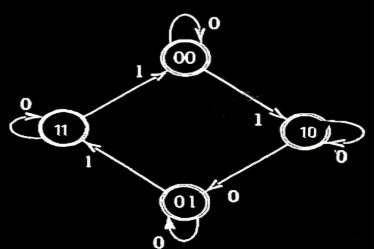
Explain the design procedure of a clocked sequential circuit. Design a clocked sequential circuit whose state diagram is given in the figure.
Write short notes on (any two):
a) State reduction table
b) Multiplexer
c) Synchronous and Asynchronous counter
Explain shift register with parallel load. Design a synchronous Mod-10 counter to count in the sequence 0,2,4,5,6,8 using T flip-flops.
And more questions available on this page.